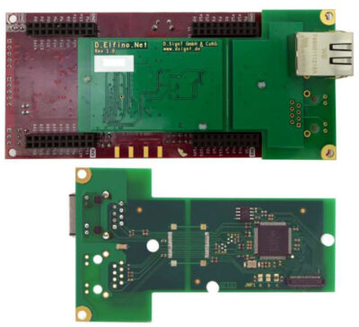
Select Page

TE0705-04

£180.00


Simplified carrier board based upon TE0701


95 in stock

Description

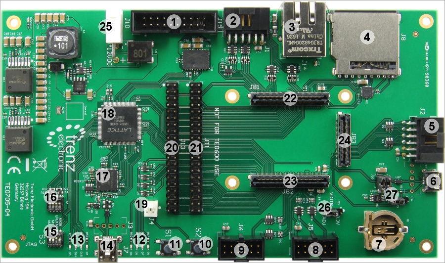
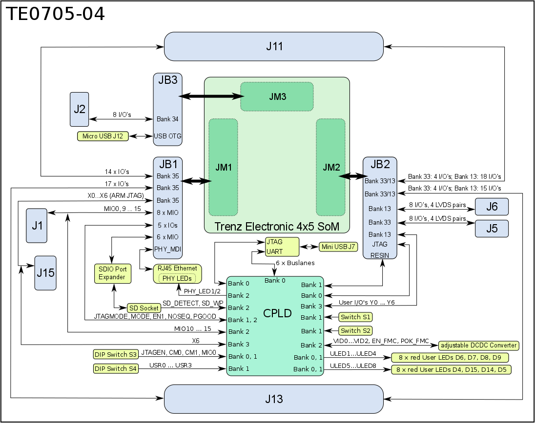
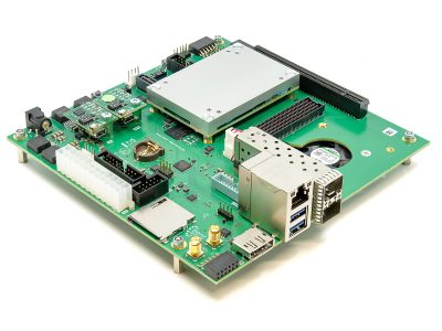
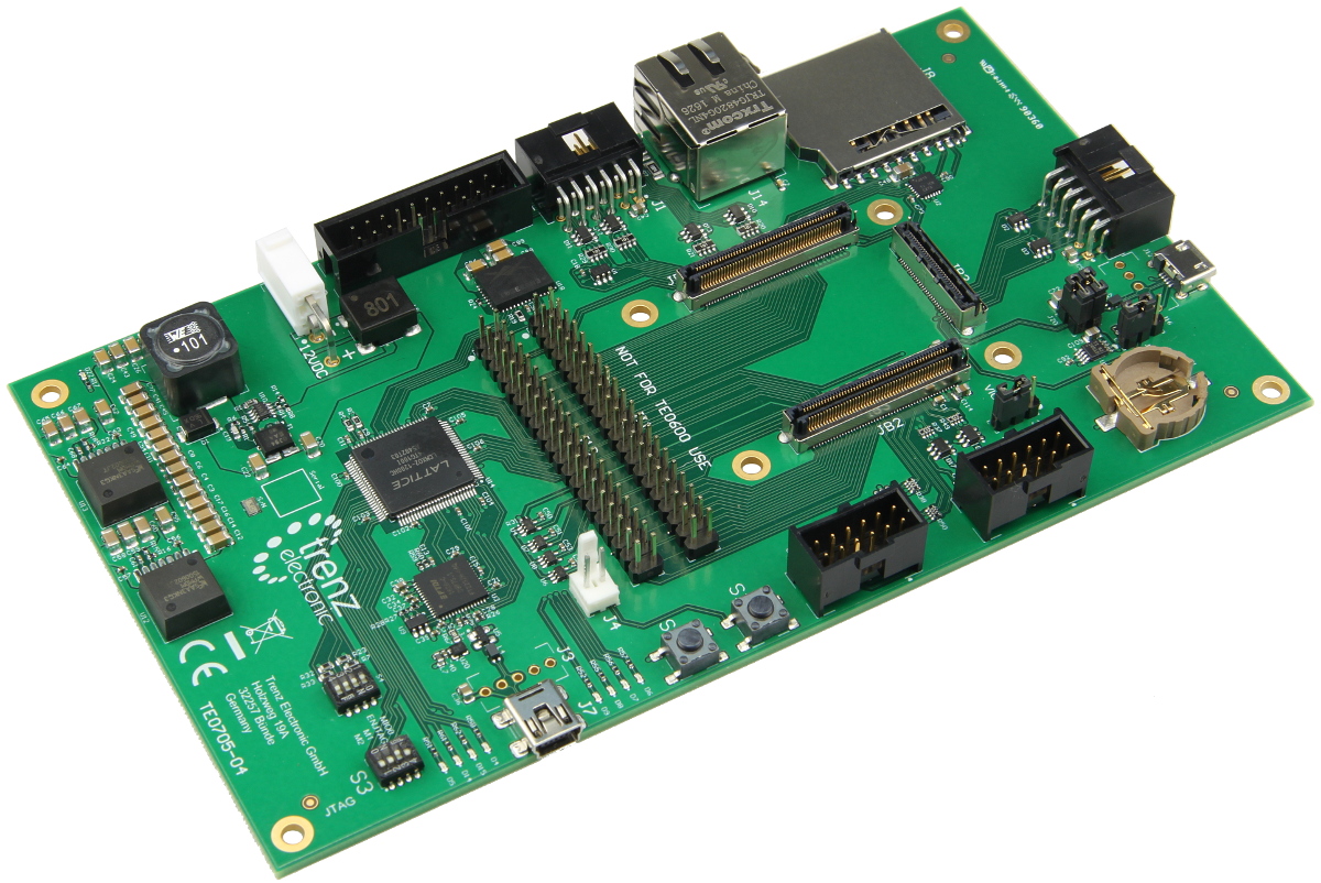
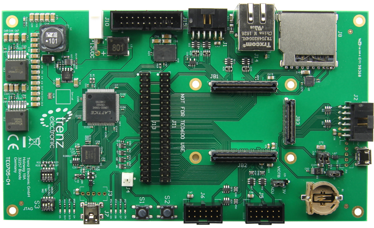
The Trenz Electronic TE0705 carrier board provides functionality for testing, evaluation and development purposes of company’s 4 x 5 cm SoMs (System on Module). The carrier board is equipped with a broad range of various components and connectors for different configuration setups and needs. On-module functional components and multipurpose I/Os of the SoM’s PL and PS logic are connected via board-to-board connectors to the carrier board components and connectors for easy user access.

Micro SD card socket is connected to the B2B connector through a Texas Instruments TXS02612 SDIO Port Expander for voltage translation. The Micro SD card has 3.3V signal voltage level while Xilinx Zynq MIO bank uses 1.8V for VCCIO.

Dual Channel USB to UART/FIFO: The TE0705 carrier board has on-board USB 2.0 high-speed to UART/FIFO IC FT2232H from FTDI. Channel A can be used as JTAG Interface (MPSSE) to program the System Controller CPLD. Channel B can be used as UART Interface routed to CPLD. There are also 6 additional bus lanes available for user-specific use.

There is also a 256-byte serial EEPROM connected to the FT2232H chip pre-programmed with license code to support Xilinx programming tools.

The baseboard TE0705 is a “downgraded” version from TE0701 and it provides low-cost connection and extension to Trenz Electronic modules with a standard footprint of 4 x 5 cm. As little as possible has been changed in functionality (except the functionality that was removed).


Do not access the FT2232H EEPROM using FTDI programming tools; doing so will erase normally invisible user EEPROM content and invalidate stored AMD/Xilinx JTAG license. Without this license, the on-board JTAG will not be accessible any more with any AMD/Xilinx tools. Software tools from the FTDI website do not warn or ask for confirmation before erasing user EEPROM content.

Features

  • Overvoltage, undervoltage and reverse supply protection controller
  • Mini-Fit JR Header 2Pol for 12V power supply
  • On-board System Controller CPLD (Lattice MachXO2 1200HC), programmable via Mini-USB JTAG interface J7
  • SoM can be programmed through System Controller CPLD via Mini-USB JTAG interface J7
  • RJ45 Gigabit Ethernet MagJack with 2 integrated LEDs
  • 2 x 40-pin headers J11 and J13 for access to module’s PL IO bank pins
  • USB JTAG/UART interface (FTDI FT2232H) with Mini-USB connector J7
  • 8 x user LEDs (red) routed to System Controller CPLD
  • 2 x user-push buttons routed to System Controller CPLD. By default (depending on CPLD firmware) configured as system “RESET” and “RESTART” buttons
  • 2 x 4-bit DIP-switch for baseboard configuration
  • 2 x 12-pin IDC header socket (vertical) J5, J6 for accessing module’s PL IO bank pins, can be used as LVDS pairs
  • 2 x 12-pin IDC header socket (right angle) J1 and J2 for accessing module’s PL IO bank pins or PS MIO0 bank pins (if used with Zynq module)
  • 2 x 50-pin IDC header J11, J13 for accessing module’s PL IO bank pins
  • Micro SD card socket with card detect switch, can be used for system booting
  • Micro-USB interface (J12) connected to SoM’s USB transceiver (Device, Host or OTG modes)
  • Trenz Electronic 4 x 5 cm module connectors (3 x Samtec LSHM series)

Labelled Image


  1. ARM JTAG Connector (DS-5 D-Stream) J15 – functionality depends on connected module
  2. 12-pin IDC header socket J1 (right angle, max. VCCIO voltage 3.3V)
  3. RJ45 GbE Connector
  4. SD Card Socket – Zynq SDIO0 bootable SD port
  5. 12-pin IDC header socket (right angle) J2
  6. Micro USB Connector J12 (Device, Host or OTG Modes)
  7. Battery holder for CR1220 (RTC backup voltage)
  8. 12-pin IDC header socket (vertical) J5
  9. 12-pin IDC header socket (vertical) J6
  10. User Push-Button S2 (“RESTART” button by default)
  11. User Push-Button S1 (“RESET” button by default)
  12. User LEDs D6, D7, D8, D9
  13. User LEDs D4, D5, D14, D15
  14. Mini USB Connector (USB JTAG and UART Interface) J7
  15. User 4-bit DIP-Switch S3
  16. User 4-bit DIP-Switch S4
  17. FTDI FT2232H USB 2.0 High Speed to UART/FIFO
  18. Lattice Semiconductor MachXO2 1200HC System Controller CPLD
  19. Jumper J4 to fix user button S2 to switched state
  20. 40-Pin-Header J13 for access to PL IO-bank-pins
  21. 40-Pin-Header J11 for access to PL IO-bank-pins
  22. Samtec Razor Beam™ LSHM-150 B2B connector JB1
  23. Samtec Razor Beam™ LSHM-150 B2B connector JB2
  24. Samtec Razor Beam™ LSHM-130 B2B connector JB3
  25. Mini-Fit JR Header 2Pol for 12V power supply J10
  26. Jumper J21 to select supply voltage of VIOTB
  27. Jumper J9, J19, J20 to select supply voltage of USB-VBUS

Block Diagram