Select Page

PXIe-PCIe8

£925.00


Allows you to connect any PXIe peripheral board directly to a PCIe x8 slot on your PC, eliminating the need for a PXIe chassis.


Description


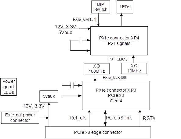
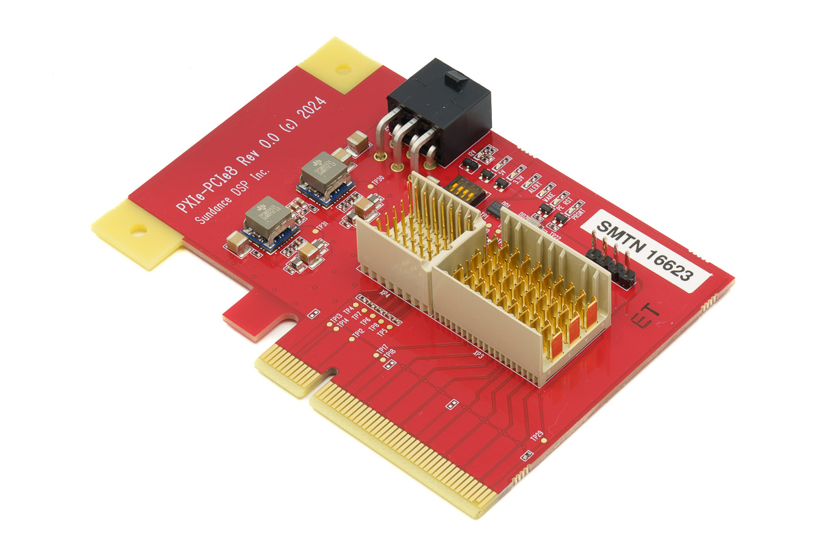
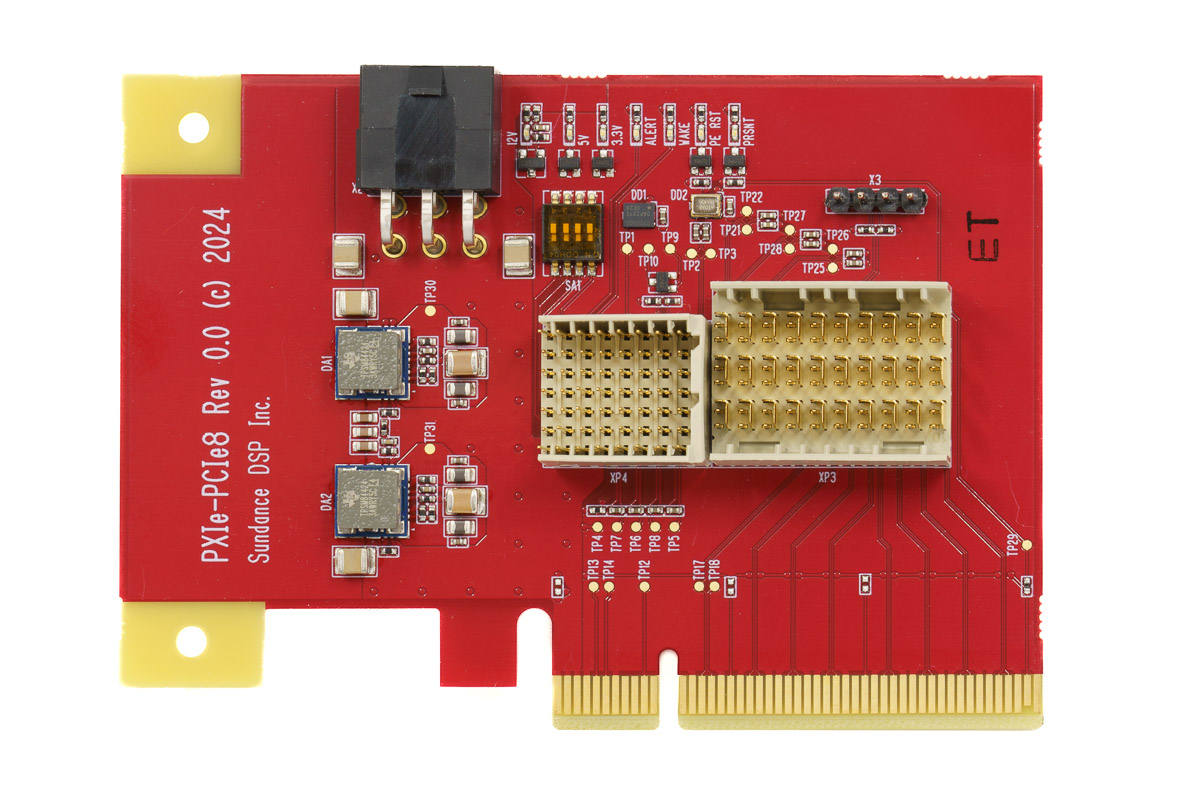
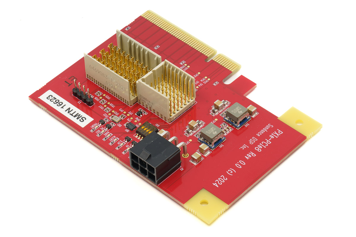
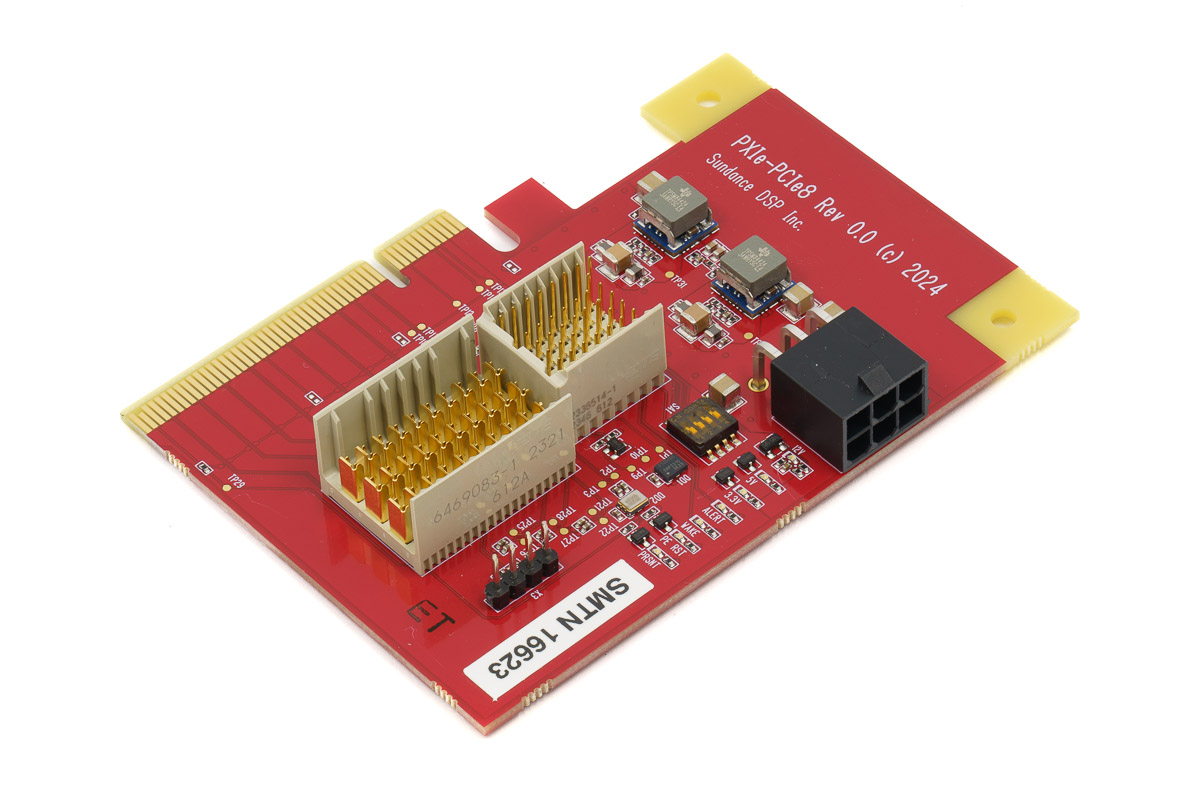
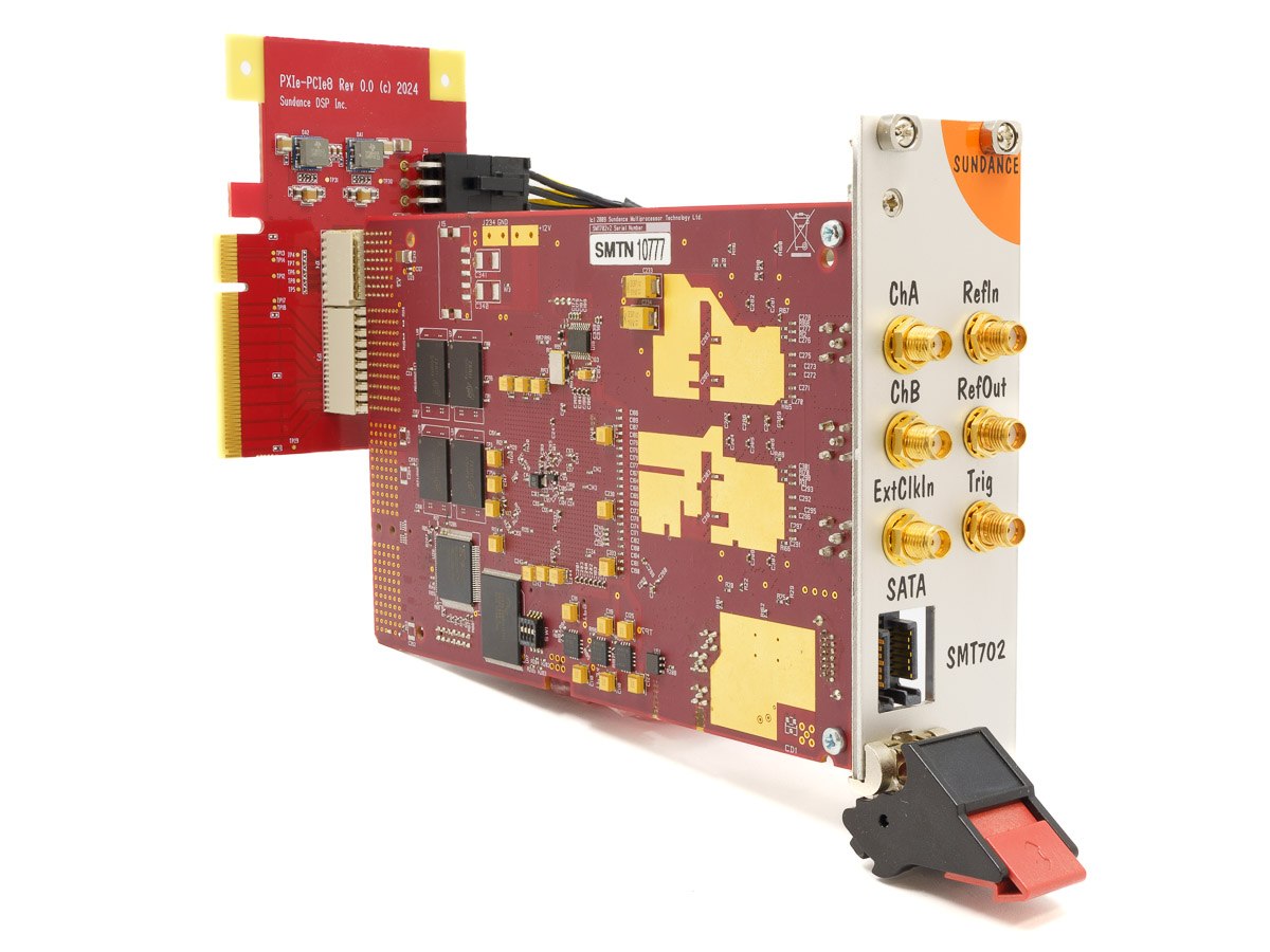
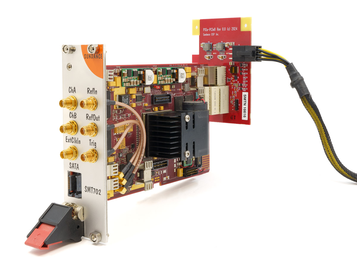
The PXIe-PCIe8  is designed for rapid firmware development and testing of PXIe peripheral 3U boards, without the need for a PXIe chassis. It allows you to connect any PXIe peripheral 3U board to your PC via a PCIe x8 interface and access its features and functions through a SMBus interface. It also provides test points and loops for measuring and monitoring PXI_TRIG and PXIe_DSTAR signals, as well as user LEDs for indicating PXI_TRIG[0,1] status. It has dip switches for selecting the slot address of the PXIe peripheral board and on-board crystal oscillators for generating 100-MHz and 10-MHz PXIe clocks. It can be powered by either the PCIe slot or an external power connector, with 12-V and 3.3-V supply voltages.

With PXIe-PCIe8, you can easily and quickly develop and test your PXIe peripheral 3U boards without investing in a PXIe chassis. It is ideal for prototyping, debugging, and validating your PXIe applications.

Features


  • PCIe x8 interface to PC: This provides a high-speed data connection between the board and the PC.
  • SMBus interface via pin header: This allows you to access and control the features and functions of the PXIe peripheral board through a simple serial bus.
  • PC PCIe slot plug-in: This enables you to plug the board into any available PCIe slot on your PC, without the need for a PXIe chassis.
  • 3U PXIe peripheral board slot: This accepts any PXIe peripheral 3U board that you want to develop and test.
  • Dip switches for slot address selection: These let you select the slot address of the PXIe peripheral board, which is required for JTAG and SMBus communication.
  • Test loops for PXI_TRIG and PXIe_DSTAR signals: These provide test points and loops for measuring and monitoring the trigger and differential star signals of the PXIe peripheral board.
  • User LEDs for PXI_TRIG[0,1] signals: These indicate the status of the trigger signals of the PXIe peripheral board, which are used for synchronization and timing.
  • On-board crystal oscillators for PXIe clocks: These generate 100-MHz and 10-MHz reference clocks for the PXIe peripheral board, which are required for data conversion and signal processing.
  • Power supply options: This board can be powered by either the PCIe slot or an external power connector, with 12-V and 3.3-V supply voltages.


Applications


  • Rapid firmware development and testing
  • High-performance data acquisition and signal processing
  • Multi-chassis system integration

Block Diagram