
Description
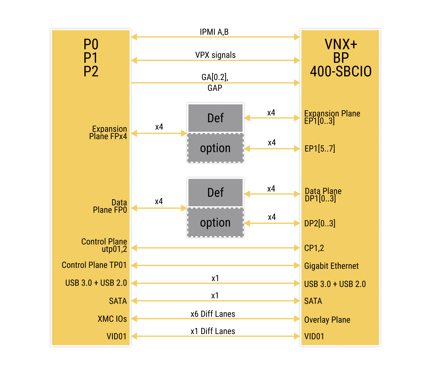
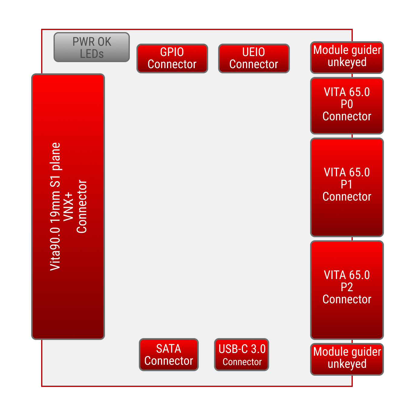
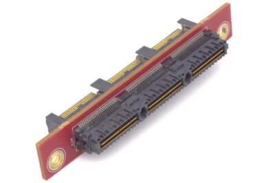
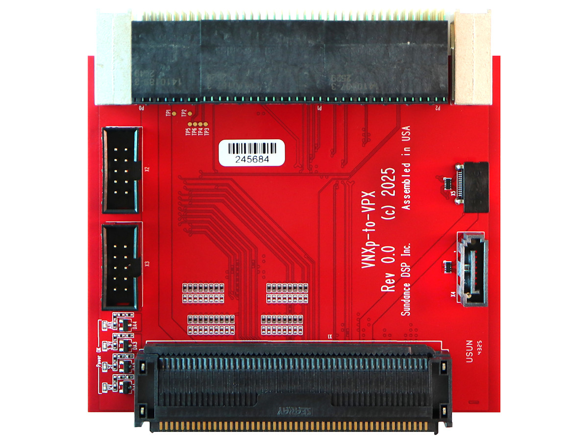
This board serves as a precision‑engineered interposer and mechanical adapter between a VNX+ 19 mm, 400‑pin SBCIO PIM (Plug‑In Module) and a SOSA‑aligned OpenVPX Payload Slot conforming to profile MOD3‑PAY‑1F1F2U1TU1T1U1T‑16.2.15‑1.
Designed to simplify system integration, the adapter enables seamless insertion of a VNX+ module into a compatible VPX backplane slot without requiring any redesign of the host system. It preserves full signal mapping between the VNX+ PIM connector and the corresponding VPX interfaces defined by the SOSA Technical Standard.
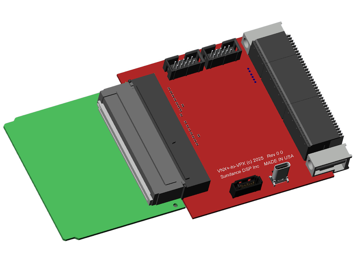
This is a fully passive interposer, containing no active components, power regulation, or signal conditioning. Its purpose is purely mechanical and electrical adaptation, ensuring:
- Correct connector alignment and form‑factor translation
- Direct pass‑through of signals between VNX+ and VPX interfaces
- Mechanical stability for ruggedised or embedded deployments
- Compliance with SOSA and VNX+ mechanical envelope requirements
This adapter is ideal for developers and system integrators who need to evaluate, prototype, or deploy VNX+ processing modules within existing VPX‑based architectures, particularly in defense, aerospace, and high‑reliability embedded systems.