Select Page

FMC-SDR400D

A platform for prototyping and developing software-defined radio applications


FMC-SDR400D User Guide


CONTACT US FOR A QUOTE
Category:

Description

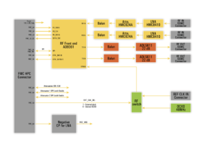
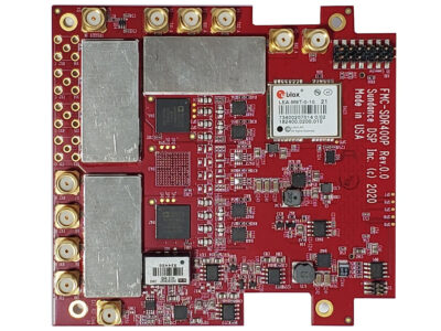
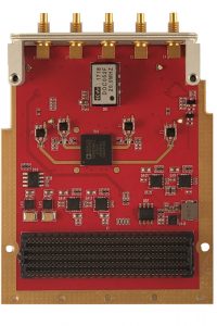
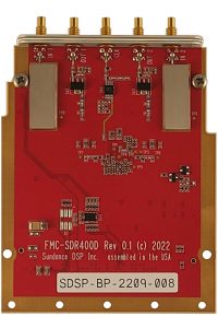
The FMC-SDR400D is a powerful platform for prototyping and developing software-defined radio applications. Based on the AD9361 Transceivers IC, it features a Low Noise Amplifier (LNA) on the RX channels and a 20 dB amplifier IC on the TX channels. Discover how this versatile board, supported by Sundance DSP IP Core, enables the creation of active antennas, receive beamforming, and angle of arrival systems.


Features

  • FMC LPC connector for interfacing with EMC²-DP carrier;
  • All electrical signals comply with Vita 57.1 FMC standard;
  • 5 SSMC RF input connectors part number – 7110-1511-000, two inputs, two outputs, one clock input;
  • RF Input specifications:
    • 50 ohm, single-ended;
    • Input frequency range 0.1 GHz – 6 GHz, input Bandwidth –up to 56 MHz;
    • Gain nonlinearity – ±3 dB*;
    • Channel gain mismatch – max 1 dB*;
    • Return loss >= 6 dB*;
    • Maximum allowable input power – 20 dBm;
  • Input LNA HMC8410LP2FE; NF = 1.6 (0.3 to 3 GHz); Gain <= 17.5 dB (parameters from IC datasheet);
  • The input tunable attenuator is HMC624A;
  • RF Output specifications:
    • 50 Ohm, single-ended;
    • Output frequency range 50MHz – 6 GHz, TX EVM <= – 40 dB;
    • Maximal output power 28 dBm at 800 MHz, 26 dBm at 2.4 GHz;
    • Gain nonlinearity – ±4 dB*;
    • Channel gain mismatch – 1 dB max
  • TX path contains 22 dB TX amplifier ADL5611;
  • 1 external reference clock input connector;
  • External reference clock input range – 10 – 80 MHz;
  • Internal 40 MHz OCXO, +-100ppb, as an option can be used 40 MHz TCXO;
  • Maximum Power consumption:
    • 12V – Max 0.6A;
    • 3V3 – Max 0.1A;
    • VADJ – Max 1A;
  • VADJ supported – 1.8V, 2.5V.

Applications

  • General Software Defined Radio
  • Radio Astronomy
  • Ship Tracking
  • Aircraft Tracking
  • GSM/3G/4G/LTE Network
  • Wireless Communications
  • Prototyping
  • Signal Intelligence
  • Medical wireless integration
  • Radar

Block Diagram

IP Cores / Drivers / BSP

The board will be supported by Sundance DSP IP Core for configuring the RF devices.